



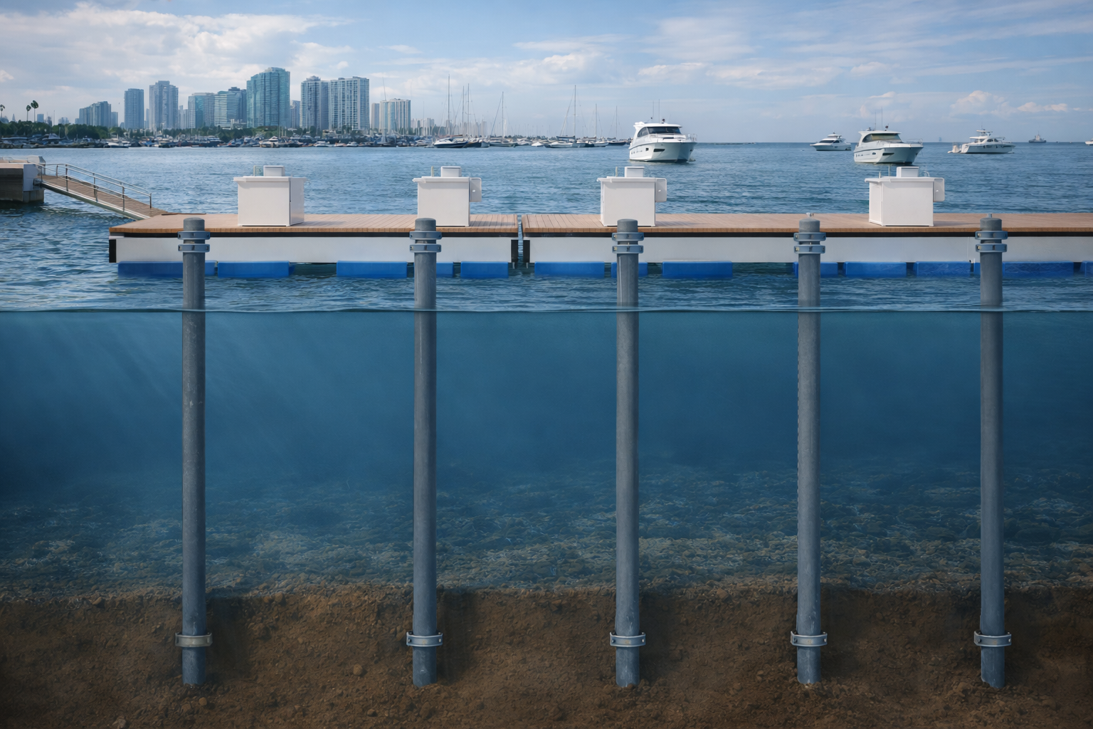
Modern waterfront investment demands more than a contractor and a catalog of dock components. A marina is a dynamic infrastructure system where structural engineering, hydrodynamic forces, vessel operations, and long-term maintenance economics all intersect. For resort developers, port authorities, real estate owners, and marina investors, understanding how these systems are designed and why they fail is the foundation of sound asset decision-making.
This guide explains the engineering logic behind high-performance marina design in plain language, without sacrificing technical accuracy.
Why Marina Engineering Is a Specialized Discipline
Marina infrastructure operates under simultaneous loads, wave action, wind, tidal variation, mooring tension, and vessel impact that inland construction never encounters. This combination demands integrated structural, hydrodynamic, and geotechnical analysis from the earliest design phase, not as an afterthought during construction.
Unlike a building or a road, a marina operates in a permanently aggressive environment where multiple degradation mechanisms act simultaneously. Steel corrodes under sustained marine exposure. Wood decays through moisture absorption, biological attack, and UV degradation. Concrete floating dock sections, particularly those reinforced with conventional steel rebar, are inherently vulnerable to chloride-induced reinforcement corrosion, which initiates spalling, section loss, and progressive structural deterioration from the inside out. Concrete is further susceptible to longitudinal bending failures: the hogging and sagging stresses generated by uneven wave loading and differential buoyancy will initiate cracking at the tension face in any section lacking sufficient flexural inertia, a predictable failure mode in a material that carries negligible tensile capacity. Pile connections fatigue under thousands of daily load reversals driven by tidal movement, wind, wave action, and vessel berthing forces.
Every element from the primary dock frame to the gangway hinge pin must perform reliably not on Day 1 alone, but continuously across a service life that typically spans 25 to 50 years under conditions that actively work to degrade it. That is why Marina Engineering Consultancy must begin at the pre-design stage. Engaging a marine engineer after layout decisions have been made is like hiring a structural engineer after the columns are poured; the most consequential choices are already locked in.
A professionally engineered marina design integrates site geometry, basin configuration, berth layout, circulation patterns, utility routing, and environmental load analysis into a unified strategy. Even incremental changes a 10% reduction in fairway width, a shift in dock orientation, can create navigation hazards, structural overstress, or operational inefficiencies that persist for decades.
Marina Master Planning: The Foundation of Asset Performance
Marina master planning is the process of translating site conditions, vessel data, and user expectations into a functional layout that maximizes berth capacity, ensures safe navigation, and protects long-term asset value. It is not a purely technical exercise it is the first and most consequential value-creation decision in waterfront development.
Effective marina master planning begins with three inputs: a thorough understanding of the vessel fleet the marina will serve, a rigorous assessment of site conditions (wave exposure, tidal range, prevailing wind and current direction), and clarity on the owner’s operational and commercial objectives.
From those inputs, the planning process defines:
- Vessel parameters: Length overall (LOA), beam, draft, and freeboard the physical dimensions that set every spacing and clearance requirement in the design.
- Berth geometry: Methodologies are detailed in Mellor (1992) and formalized in ASCE Manual 50. Additional guidance on basin protection and channel design is available through USACE EM 1110-2-1615. Slip widths are typically calculated as LOA/3.74 + 2.13 m for powerboats in the 9–25 m range; larger vessels require individualized berth analysis.
As a worked example, the Azimut Magellano 25 metri has a Length Overall of 25.22 m (82′ 9″) and a Beam Max of 6.30 m (20′ 8″): 25.22 m / 3.73 + 2.13 m = 8.87 m (29’–1″), leaving a total clearance of 2.57 m (8’–5″) approximately 1.28 m (4’–2″) per side for fenders and lateral movement within the slip.
- Fairway dimensions: Widely adopted industry practice recommends minimum fairway width that scales with vessel size 1.5× LOA for vessels under 15 m in protected basins, increasing to 2.0× LOA for mid-range vessels and 2.5–3.0× LOA for superyachts and multihulls requiring wider turning clearances.
- Basin protection: The orientation of the marina entrance, breakwater configuration, and dock layout must collectively minimize wave energy reaching berths.
- Environmental alignment: Vessels oriented parallel to prevailing wind reduce radial load on pile systems and decrease vessel swing within slips.
A well-planned layout is not simply easier to navigate it is a commercially stronger asset. Higher berth utilization, lower insurance exposure, reduced operational incidents, and simpler future expansion are all downstream benefits of rigorous master planning.
Floating Dock Systems: Engineering Principles and Performance Logic
Floating dock systems maintain constant freeboard the distance between deck and water surface regardless of tidal or water level changes, making them the standard choice for sites with more than 0.5 m of water level variation. Structurally, a floating dock behaves like a continuous marine beam: it must carry live loads uniformly while remaining flexible enough to accommodate wave-induced motion.
A complete floating dock system is an assembly of interdependent components:
- Structural frame: Marine-grade extruded aluminum alloy (typically 6061-T6 or 6005A-T6) provides the primary structural skeleton. Aluminum’s high strength-to-weight ratio reduces dead load on flotation units and minimizes pile loads.
- Flotation units: Closed-cell expanded polystyrene (EPS) or rotationally molded polyethylene billets provide buoyancy. Flotation sizing must account for both uniform distributed loads and concentrated point loads.
- Decking: Options include hardwood timber (IPE, Teak), composite, aluminum grating, and poured concrete. Material selection affects slip resistance, maintenance frequency, thermal comfort, and aesthetics.
- Fender systems: Continuous rubber or polyethylene fenders protect dock edges and vessel hulls from contact damage during berthing and surge events.
- Mooring hardware: Cleats, bollards, and slides must be sized for the design vessel’s mooring line loads.
The critical performance parameter is deflection control. A dock that flexes excessively under live load is uncomfortable and unsafe; one that is too rigid generates constraint forces at connections, accelerating fatigue failure. This balance stiffness against flexibility defines the structural design problem.
Floating Dock Cross Section: What Matters Most for Long-Term Performance
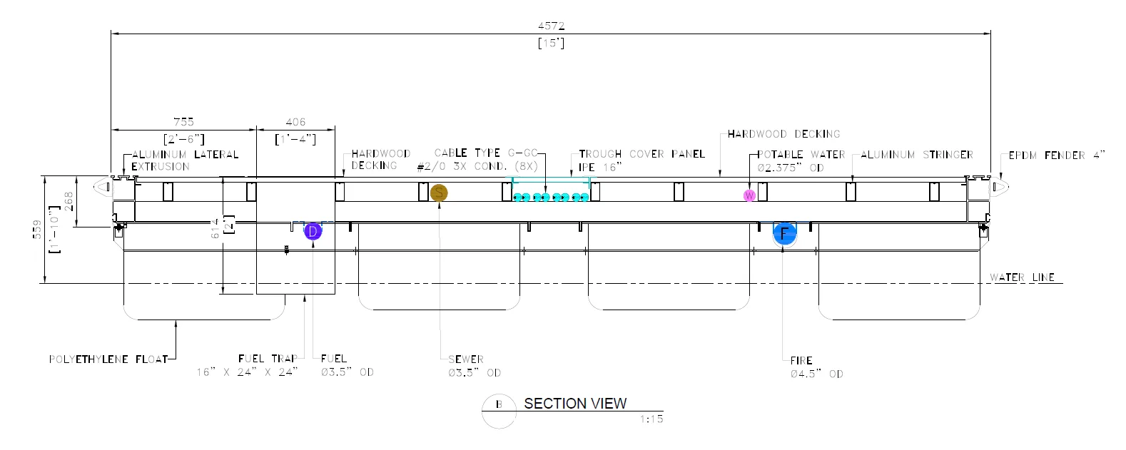
The cross section of a floating dock reveals how structural depth, flotation position, decking type, and hardware attachment interact as a unified system. A well-designed cross section ensures that loads transfer efficiently from the walking surface through the frame into the flotation without creating stress concentrations at connections or allowing water infiltration into structural members.
Structural Depth and Stiffness
Greater frame depth increases bending stiffness under gravity loads (service carts, pedestrians, dock boxes, utility pedestals), reducing midspan deflection under live load conditions. In practice, dock depth is balanced against freeboard requirements and aesthetic preferences. Lateral stiffness is equally critical the dock frame acts as a horizontally loaded truss under berthing impact and mooring line forces, which must be transferred efficiently to the pile guide system.
Weld Zone Integrity
For welded aluminum dock frames in 6005A-T6, the heat-affected zone (HAZ) adjacent to each weld experiences a reduction in yield strength of approximately 54% relative to the parent material. This makes wall thickness selection in lateral extrusions a governing design parameter particularly at connections subject to cyclic fatigue from wave action and repeated berthing loads over the service life of the structure.
T-Slotted Extrusion Profiles
A significant advantage of aluminum extrusion is the ability to incorporate integrated T-slot channels directly into the structural frame. Hardware cleats, bollards, ladders, and safety stations can be installed, repositioned, or replaced using T-bolts without drilling into structural members. This preserves section integrity, eliminates corrosion initiation sites at penetrations, and provides long-term operational flexibility for marina operators.
Fastener Selection and Galvanic Corrosion Management
Stainless steel fasteners in aluminum structures require careful specification to manage galvanic corrosion potential. In aggressive marine environments such as the Caribbean, the Gulf, and the Middle East the use of isolating layers, marine-grade sealants, and appropriate alloy pairing (316L stainless steel with aluminum) is standard practice in premium dock systems.
Walking Surface Performance
Slip resistance is non-negotiable. Wet dock surfaces in marine environments become hazardous rapidly. Aluminum extruded planks with integrated traction ridges, composite decking with anti-slip profiles, and tropical hardwood finishes each address this requirement differently. Selection should reflect site climate, expected user profile, barefoot traffic considerations, and long-term maintenance capacity.
Pile Guide Systems: The Often-Underestimated Structural Link

Pile guides are the interface between the floating dock and its vertical support piles. They allow controlled vertical motion docks rise and fall with water levels while resisting lateral forces from wind, waves, vessel impact, and current. Inadequate pile guide design is one of the most common causes of marina structural failure and accelerated system degradation.
A floating dock without well-designed pile guides is a boat without a keel. Lateral stability is not optional it is what keeps dock geometry consistent, prevents progressive misalignment, and protects pile connections from uncontrolled bending moments.
Pile sizing and embedment must be designed for the full environmental load envelope: wind loads on moored vessels, wave-induced lateral forces, and vessel impact during berthing. In cold-climate marinas, ice load both static pressure from sheet ice and dynamic impact from ice floes, must also be quantified and incorporated.
Embedment depth is a geotechnical question as much as a structural one. Pile performance depends on soil stiffness, lateral bearing capacity, and scour potential. In soft sediment sites, embedment depths that appear adequate on paper can produce unacceptable deflections under storm loading.

Conventional roller-type pile guides typically have solid UHMW-PE rollers that concentrate contact stress at small bearing areas and function effectively only under vertical movement. Under real-world radial forces from wave action, vessel berthing impact, and tidal fluctuation, UHMW rollers deform progressively, develop flat spots, and eventually seize within their housings converting a rolling contact into static friction against the pile. High-performance pile guide systems such as ShockGUARD distribute lateral loads across a significantly larger contact surface, absorb dynamic impact energy before it reaches the primary structure, and deliver substantially longer service life under repeated loading.

Gangways and Shore Access: Where User Experience Meets Engineering Compliance
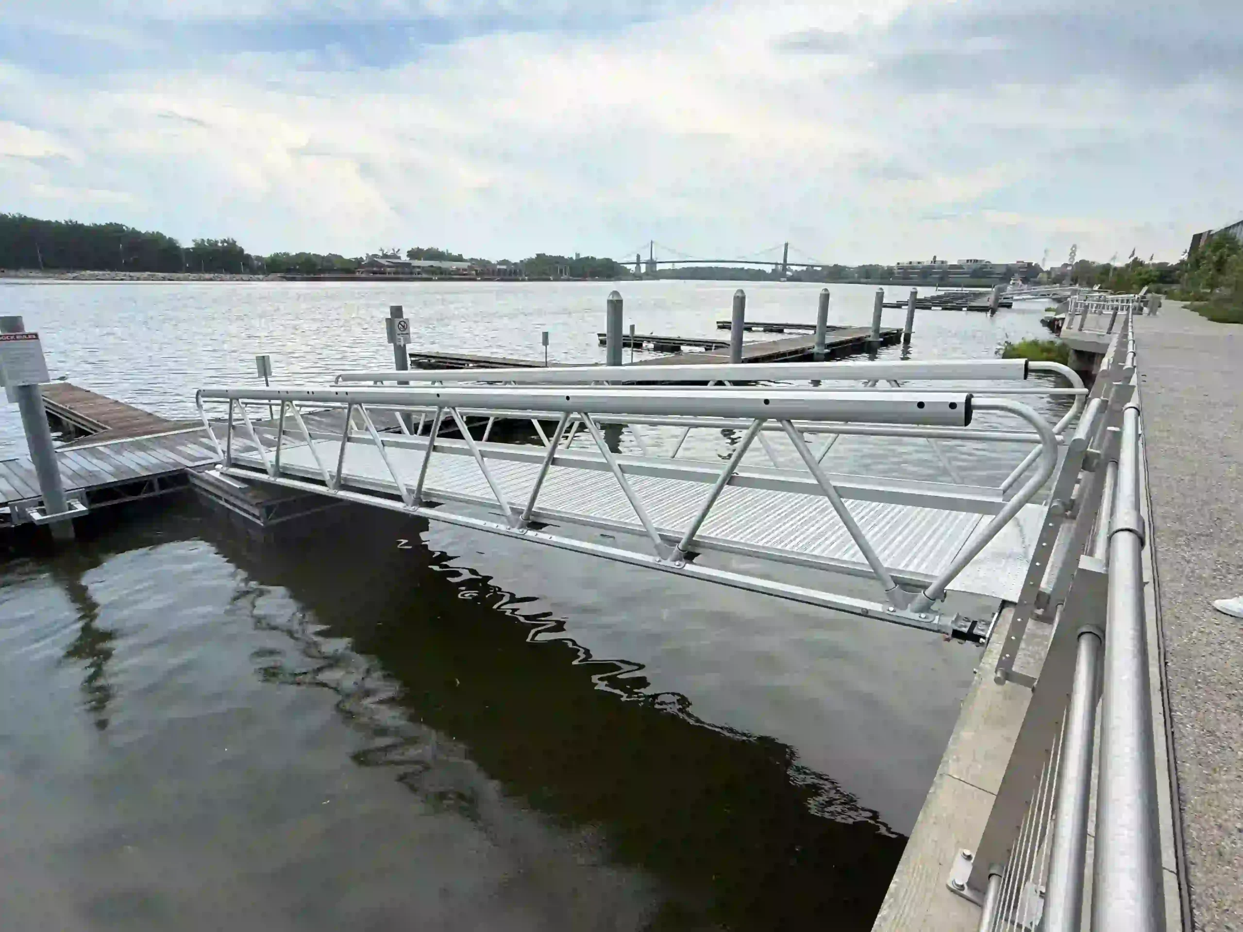
Marina gangways connect the fixed shoreline to the floating dock system. They must accommodate the full range of water level change from annual tidal and seasonal variation to extreme surge events while maintaining safe pedestrian access and, where required, compliance with ADA accessibility standards for slope, width, and edge protection.
Gangways are the most visually prominent element of any marina facility typically the first structure a visitor encounters. Yet they are routinely underengineered. Many manufacturers treat gangways as commodity items, supplying functional but minimally designed structures that prioritize cost reduction over structural refinement, visual integration, and long-term durability. In premium waterfront developments where the gangway sets the first impression for guests, investors, and regulatory officials this approach creates a visible disconnect between the quality of the marina and the quality of its most public-facing element. A gangway that deflects noticeably underfoot, lacks proportioned handrail detailing, or shows premature surface degradation undermines the perceived value of the entire facility.
Purpose-engineered gangway systems now address this gap offering clear anodized aluminum finishes that resist oxidation and pitting corrosion in aggressive marine exposure, integrated LED lighting for safe nighttime access, and structurally optimized truss geometry that controls deflection across the full span under pedestrian and service loading.

Slope management is the central design challenge. The ADA 2010 Standards (Section 1003) require a maximum gangway slope of 1:12 (8.3%) under typical water level conditions. For gangways 80 feet or longer, the ADA provides slope flexibility to accommodate tidal fluctuation but only when the overall gangway length provides adequate run. Designing gangways to the lowest expected water level, not the average, is the baseline for compliant and safe access.
Structural loading includes pedestrian live loads, service cart loads (fuel, provisioning, luggage), wind-induced vibration, and the dynamic forces generated by wave action at the floating dock connection. In exposed locations, gangway oscillation under wind loading must be assessed both for structural integrity and for user comfort.
Connection detailing at both ends of the gangway is critical. The shore-end connection must accommodate longitudinal movement as the floating dock shifts laterally and vertically. The dock-end connection must allow rotation in multiple axes without binding, which would transfer unintended constraint forces into both the gangway and the dock frame.
In premium resort and residential marina environments, gangways also serve a design function they establish the visual language of the waterfront. Material finish, railing profile, and illumination strategy all carry aesthetic weight disproportionate to the gangway’s structural simplicity.
Marina Layout Engineering: Turning Geometry Into Revenue
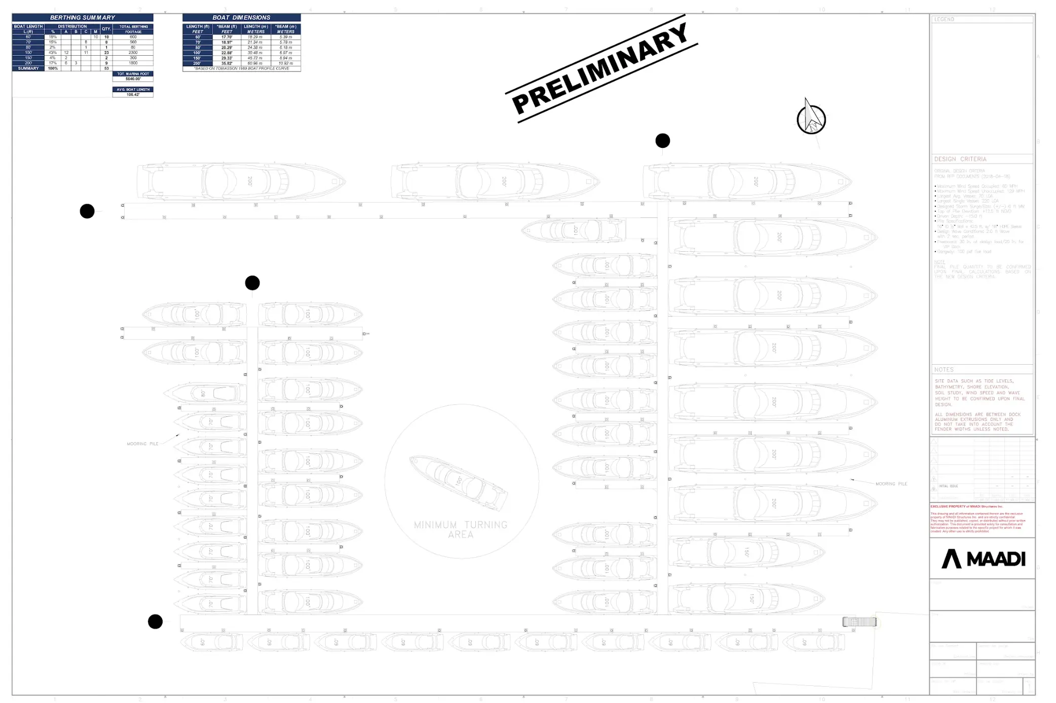
Marina layout engineering translates environmental data, vessel dimensions, and commercial objectives into a berth arrangement that is safe to navigate, efficient to operate, and financially optimized. Poor layout decisions made during design cannot be corrected cheaply after construction the cost of redesigning a poorly performing layout often exceeds the original engineering fee by orders of magnitude.
Slip organization should group vessels by size class, not by arbitrary sequence. Vessels of similar LOA and beam require similar fairway widths and maneuvering clearances. Mixing small recreational boats with large yachts in the same fairway either wastes space (designing to the largest vessel) or creates hazards (designing to the smallest).

Turning basins at fairway terminations must provide sufficient radius for the largest intended vessel to reverse direction without requiring external assistance. For vessels above 20 m LOA, this is a non-trivial spatial requirement that directly affects total marina footprint.
Wind and current alignment: Berths oriented so that vessels enter their slip with prevailing wind and current on the beam or stern rather than on the bow reduce the skill demand on vessel operators, decrease berthing incident rates, and improve overall user satisfaction.
Basin protection: Wave energy entering the marina basin must be attenuated to levels compatible with safe berthing and comfortable stay. The relationship between breakwater configuration, entrance geometry, and interior wave climate is modeled hydrodynamically not estimated. Under-protected basins expose every structural element to accelerated fatigue loading on flexible rubber connectors and pile guides.
Load Analysis: What Marina Structures Must Withstand
Marina structures are exposed to multiple simultaneous load types wind, waves, current, mooring tension, berthing impact, pedestrian use, and in cold climates, ice that rarely act in isolation. Accurate structural design requires modeling these combined load cases, not treating each force independently.
Understanding the load environment is foundational to evaluating any marina investment. The following load types govern structural sizing in typical commercial marina design:
| Load Type | Primary Design Consideration | |
| Wind loads on moored vessels |
|
|
| Wave and current action |
|
|
| Berthing impact |
|
|
| Pedestrian and service loads |
|
|
| Ice loads (cold climates) |
|
|
| Surge and uplift |
|
Design standards for marina structures reference ASCE 7 (Minimum Design Loads for Buildings and Other Structures) for wind and snow loading, and site-specific hydrodynamic analysis for wave and current conditions. Coastal structures in FEMA-designated flood zones have additional requirements under ASCE 24 and NFIP technical bulletins.
The engineering challenge is not any single load case in isolation it is the simultaneous combination of multiple loads at peak intensity. A storm event that combines surge, wave action, and high wind on a fully occupied marina applies compound forces to every structural element at once.
Material Selection for Floating Dock Systems: Aluminum, Concrete, and Wood Compared
Aluminum is the dominant structural material in modern commercial floating dock systems because it combines high strength-to-weight ratio, excellent corrosion resistance, and 30–50+ year structural service life with minimal maintenance. Wood offers lower upfront cost but carries higher lifecycle cost; concrete delivers durability but imposes high dead loads that cascade into increased flotation and pile demands.
Material selection is not a procurement decision it is a lifecycle engineering decision.
Aluminum
Structural service life spans 30–50+ years with routine cleaning alone. No protective coating, painting, or chemical treatment is required. Aluminum’s relatively low modulus of elasticity (approximately 70 GPa, compared to 200 GPa for steel) provides an inherent structural advantage in dynamic marine environments dock frames deflect and absorb energy under storm loading, wave action, and torsional demands rather than resisting rigidly. This elastic flexibility allows the material to accommodate transient peak loads through reversible deformation well within its elastic range, reducing the accumulation of fatigue damage at connections and welds over the structure’s service life.
Aluminum forms a passive oxide layer that limits further corrosion. In saltwater environments, marine-grade alloys (5083, 6061) are standard. Galvanic corrosion at contact points with dissimilar metals must be managed through proper specification.
Aluminum density is approximately 2,700 kg/m³ (169 lb/ft³) roughly one-third that of steel (7,850 kg/m³ / 490 lb/ft³) and comparable to reinforced concrete (2,400 kg/m³ / 150 lb/ft³), though aluminum requires significantly greater section depth to achieve equivalent structural capacity. In practice, a comparable aluminum floating dock weighs 60–70% less than its concrete equivalent and 50–60% less than a steel alternative. This weight reduction compounds across the entire system smaller flotation units, lower lateral loads on pile guides, reduced foundation demands, lighter gangway reactions, and simplified installation logistics. For facility owners, this translates into lower capital cost at every connected component, not just the dock frame itself.
Maintenance requirements are minimal: periodic inspection of connections and fender systems, with no surface treatment needed. Aluminum is best suited for commercial marinas, resort facilities, port authority infrastructure, and any high-use environment where maintenance access is constrained or downtime is costly.
Wood (Pressure-Treated Timber)
Structural service life runs 15–25 years with regular treatment; untreated wood in marine exposure can fail within 5–10 years. Wood is susceptible to biological decay, UV degradation, moisture absorption, and fastener corrosion. Pressure treatment with copper-based preservatives raises environmental concerns. Maintenance demands are high periodic cleaning, sealing, treatment, and board replacement are all necessary, and costs compound significantly over a 20-year ownership period.
Dead load is moderate: lower than concrete but higher than aluminum per unit of structural capacity. Wood is best suited for low-budget applications, temporary installations, or contexts where natural aesthetic is the primary driver.
Concrete
Structural service life spans 35–50+ years with proper design and adequate concrete cover over reinforcement. Dead load is high, which substantially increases flotation unit requirements and raises both first cost and long-term maintenance complexity. Structural maintenance is moderate to low, though flotation system maintenance demand increases with higher dead load.
Concrete is best suited for fixed structures, heavy commercial wharves, ferry terminals, or sites where vandalism resistance or permanence is a governing requirement.
Common Marina Design Mistakes That Destroy Long-Term Asset Value
The most expensive marina failures originate in design decisions, not construction deficiencies. Six failure modes account for the majority of premature degradation, costly remediation, and reduced asset value in marina infrastructure and all six are preventable with competent engineering at the front end.
1. Structural Undersizing
Pile embedment depth, member sizing, connection capacity, and decking selection must be proportioned for the full envelope of environmental and operational demands including extreme events. Designing for average conditions and hoping for the best is not engineering; it is liability creation. A 100-year storm event has a 1% annual probability of occurring over a 50-year asset life, the probability of experiencing such an event exceeds 39%.
2. Rigid Connections in Dynamic Systems
Marina structures move vertically with tides, laterally with wind action, and rotationally under wave loads. Rigid connections where movement must be accommodated generate unintended constraint forces. These forces accelerate wear, initiate fatigue cracking at weld toes and bolt holes, and shorten service life.
3. Inadequate Pile Guide Design
Conventional roller-type pile guide assemblies concentrate contact stress at small bearing areas and perform well under their intended function, accommodating daily vertical tidal travel along the pile. However, rollers are inherently limited when subjected to the cyclic radial loads imposed by vessel berthing under wind gusts, wave action, and surge events. These radial forces act perpendicular to the roller axis, exceeding the design intent of the assembly. Under repeated loading, UHMW-PE rollers deform progressively through creep and surface wear, develop flat spots, and ultimately seize within their housings, converting a rolling contact into static friction against the pile. Once a guide assembly seizes, the dock loses its designed vertical freedom. The resulting constraint forces propagate into the dock frame, accelerate fastener fatigue at guide brackets, and initiate progressive structural misalignment that compounds with every tidal cycle. Replacement at this stage is no longer maintenance it is structural remediation.
4. Gangway Slope Miscalculation
Gangway slope at low water is consistently underestimated during design. Engineers who size gangways to average water levels not to historic low water, deliver facilities that are dangerously steep during dry seasons, drought conditions, or extreme low tide events.
5. Material Incompatibility and Galvanic Corrosion
Placing dissimilar metals in direct contact within a marine environment creates an active electrochemical cell and the rate of deterioration is directly proportional to the aggressiveness of the exposure. In high-humidity, salt-spray environments such as the Caribbean, the Gulf Coast, and the Middle East, galvanic corrosion can initiate visible material loss within less than a decade of installation. The failure mechanisms are well understood and entirely preventable: steel fasteners in aluminum frames, bronze fittings in direct contact with aluminum extrusions, and stainless steel bolts installed without dielectric barriers will establish galvanic couples that preferentially consume the less noble material invariably the aluminum structural member. Proper material specification, alloy pairing (316L stainless with aluminum), and systematic use of isolation detailing eliminate this risk at the design stage, at negligible cost relative to the structural consequences of inaction.
6. Suboptimal Basin Layout
Navigation conflicts, insufficient vessel turning radii, and dock orientation misaligned with prevailing environmental forces are among the most expensive design errors because they are the hardest to correct after construction.
The Case for Lifecycle Thinking in Marina Investment
Evaluating marina infrastructure on first cost alone produces systematically poor investment decisions. A system with a 30% higher capital cost but a 50-year structural life, minimal maintenance burden, and lower operational risk delivers significantly better total return than a low-bid system requiring major intervention every 10–15 years. Lifecycle cost modelling standard practice in airport, highway, and building infrastructure should be applied to marina investment with the same rigor.
Waterfront maintenance is materially more expensive than equivalent inland maintenance. Underwater repairs require dive crews. Limited access elevates mobilization costs. Marine exposure accelerates degradation rates. And operational disruptions during repair, closed berths, displaced tenants, halted services carry revenue consequences that never appear in a construction budget.
A life cycle cost model for marina infrastructure typically covers a 25–50 year study period and simulates the gradual deterioration of individual elements, pile systems, dock frames, fender systems, electrical infrastructure, and gangways to estimate repair timing and cost. AAPA Seaports lifecycle cost guidance identifies three primary maintenance strategies: reactive repair (after failure), preventative maintenance (before capacity is compromised), and full replacement, each with distinct cost profiles over time.
The most defensible investment position is a well-engineered, durable system with a documented maintenance plan, not the lowest construction bid. For premium resort developments, port authority infrastructure, and large-scale residential marinas, this distinction separates facilities that appreciate in value from those that become liabilities.
Frequently Asked Questions
What is marina design and why does it require specialized engineering?
Marina design is the integrated process of planning, engineering, and configuring a waterfront facility, including basin layout, floating dock systems, pile foundations, gangways, and utility infrastructure, to perform safely and efficiently over a 25–50 year service life. It requires specialized engineering because marinas operate under simultaneous structural, hydrodynamic, and environmental loads that inland structures never encounter, including wave action, tidal variation, corrosive marine exposure, and dynamic vessel mooring forces.
How wide should marina fairways be?
Fairway width depends on the size of the vessels using the marina. Industry guidelines recommend a minimum of 1.5× LOA for vessels under 15 m in protected basins, increasing to 2.0× LOA for mid-range vessels and 2.5–3.0× LOA for superyachts and multihulls requiring wider turning clearances. These dimensions ensure vessels can enter and exit slips safely without requiring tug assistance or creating navigation hazards.
What is the best material for floating dock systems?
Aluminum is the preferred structural material for commercial and resort marina floating dock systems. It offers a 30–50+ year structural service life, high strength-to-weight ratio (which reduces flotation and pile load demands), and minimal maintenance requirements in marine environments. Wood carries a lower upfront cost but a higher lifecycle cost due to maintenance intensity and shorter replacement cycles. Concrete provides durability but imposes high dead loads that increase system complexity and cost.
What ADA requirements apply to marina gangways?
Under ADA 2010 Standards (Section 1003: Recreational Boating Facilities), marina gangways must maintain a maximum slope of 1:12 (8.3%) under typical water level conditions, provide a minimum clear width of 36 inches, include handrails on both sides at 24–36 inches above the walking surface, and incorporate slip-resistant surfaces and edge protection. Gangways 80 feet or longer are granted slope flexibility to accommodate tidal variation.
What are the most common causes of marina infrastructure failure?
The six most common causes are:
- Structural undersizing: members and pile embedment not proportioned for the full load envelope, including extreme events.
- Rigid connections in dynamic systems generate fatigue-inducing constraint forces.
- Inadequate pile guide design, leading to dock misalignment and accelerated wear.
- Gangway slope miscalculation, producing inaccessible and unsafe access ramps at low water
- Material incompatibility and galvanic corrosion between dissimilar metals.
- Poor basin layout that creates navigation hazards and cannot be corrected without demolition.
Engineering Is the Differentiator
A marina is one of the most demanding infrastructure asset classes in the built environment. It operates continuously under compound environmental loading, in a corrosive medium, with daily dynamic use, and it has done so for decades. The facilities that perform, retain value, and attract premium tenants are not the ones built to the lowest bid. They are the ones engineered with precision from the first site assessment to the last connection detail.
For resort developers, port authorities, real estate investors, and governments managing coastal infrastructure, the engineering quality of a marina is not a technical footnote it is the foundation of the asset’s commercial performance.
If you are planning a new marina facility, expanding an existing one, or evaluating the structural condition of a marina you own or are acquiring, engage a specialist marine engineering team before any design or procurement decisions are made.
Contact MAADI Group for a marina engineering assessment.
View our Marina Engineering Project Portfolio.


